 Evening in Mpeketoni town
Since the big 150 kVA generator went down we have not had enough capacity to meet the load during the day and night. However, the overhaul was completed on the second small generator so we now have two operating gensets – one rated at 60 kVA and the other rated to 57 kVA. Unfortunately having two small gensets doesn’t allow us to meet more demand unless the two generators can be run in parallel.
To run two or more generators in parallel, you must first synchronize the generators so that they are operating at the same voltage, at the same frequency, and are both producing power in phase. If these conditions are not met one generator will act as a load for the other one and cause all sorts of problems, so it is very important that the process is done right.
The generators produce AC power on three separate lines or phases, here they call it the Red phase, the Yellow phase, and the Blue phase. Each phase has a similar sinusoidal pattern to the voltage and current, but the phase of the pattern is shifted by 120 degrees between the three phases.
The synchronization process ensures that the AC pattern on the Red phase of Gen1 is in phase with the Red phase of Gen2. If they are in phase then both the Yellow and Blue phases will be in phase between the generators.
MEP has a synchronization panel that is used to synchronize the generators. The main components of the panel are three switches: one switch for each generator and one for the load. If all switches are closed then the Red phase of Gen1 is electrically connected to the Red phase of Gen2 and the Red phase of the load. However, the switches for the two generators include a safety feature that doesn’t allow the switch to be closed if there is a large voltage difference across the switch.
To synchronize the generators the panel has three dials to help with synchronization. The first is a frequency meter for each generator (f). The setting on the governor of each generator is adjusted until the frequency (or rotational speed of the engine) is exactly the same as the other generator (f1=f2). The next dial indicates the voltage of each generator (V). The voltage is controlled by an accessory called the AVR or Automatic Voltage Regulator on each generator. You next adjust a setting on each generator’s AVR until the voltage on each generator is exactly the same (V1 = V2). The last dial is called the zero voltage dial. The dial indicates the voltage difference between the Red phase of each generator (V0). Only when the frequency and voltage of the two generators is the same and the lines are in phase will the zero voltage dial drop to zero (in phase only if V0 = 0).
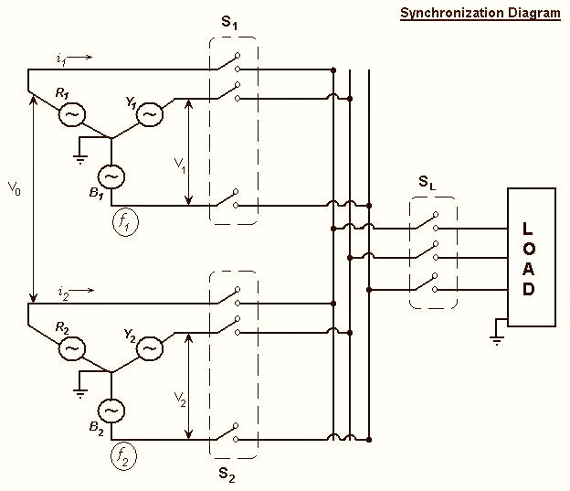 Wiring diagram for synchronization process
Once the zero voltage dial drops to zero, you can close the switches between the generators (S1 and S2). The generators are now synchronized. When the load switch is open and the generators are synchronized, there should be no current flow on any of the lines (i1=i2=0).
If everything goes okay with the synchronization, you can now close the load switch (SL) and start providing power with the two generators (now i1 and i2 are set by the load). Even if you only use one generator at a time, you still use this same panel, you just leave the switch open to the generator that will not be in use. At this time we can use either generator on its own to run the load, so we know all of the switches and circuitry are in order.
 Phanuel Mwaimbe, the manager of MEP
Here is the problem. We are able to match the frequency and the voltages between the generators and when the zero voltage dial drops to zero we are able to close both generator switches (S1 and S2). However, when we close the switches the current meters in each phase on both generators quickly climb to very high currents even when the load switch is still open. The frequencies remain equal and the zero voltage dial (V0) remains stable showing zero volts. After about 30 seconds or so the generators trip off and stop producing current. As soon as they trip off the synchronizing panel opens the two generator switches as they loose synchronization.
Normally with one generator, when you engage the load the currents quickly climb and you hear the diesel engine suddenly change sounds as it struggles to meet the new high load. However, when we close the two generator switches in the synchronization process and the currents quickly climb we do not hear the diesel engine change noises; it sounds as through the engines remain idling even with extremely high currents.
 Young girl enjoying an evening in Mpeketoni
Since the line-to-line voltage is positive and the line currents are positive, the generator apparent power (kVA) is very large. However, since there is no load and we do not hear the diesel engine sound change we can infer that the real power (kW) is close to zero. The power factor is the ratio of the real power to the apparent power (kW/kVA), which in this case is zero. A zero power factor indicates the currents are 90 degrees out of phase with the line voltages and that all of the apparent power is made up of what is called reactive power (kVAR). I’m guessing that since there are only the two generators connected to each other and no other equipment, the reactive power is due to one generator acting as a purely inductive load to the other generator. In other words one generator is producing kVARs and the other is consuming kVARs.
 Kulia, one of the MEP casual workers, installing a new section of three phase line
The question is why are they acting that way and how do we stop it? Unfortunately, the synchronizing panel doesn’t have any documentation or instructions and none of the current staff was around when the panel was first installed. At least one of the staff was around when they were still using the panel just over a year ago, so we are positive that it worked with these generators before one of them was taken off line for a major overhaul (which included rewinding the stator of the generator).
The only clues we were able to find are from past letters filed away in the MEP records. The first one is from the commissioning of the panel in 1998. The letter indicates that the panel was installed and appears to be working, but that it cannot be used to run the generators in parallel because of high “inter-circulating currents”. They blame these currents on differences in excitation of the rotors. The excitation can be adjusted by changing the “voltage droop” setting on the Automatic Voltage Regulator (AVR) which controls the excitation through a “droop current transformer” or droop CT. Adjusting the voltage droop allows you to minimize the inter-circulating currents. The letter goes on to state that the droop CTs were not installed so these currents could not be minimized until they are installed.
A second letter from 2000 indicates that the droop CTs were installed and the synchronization of the generators was successful. The installers trained the MEP technician on the synchronization process and passed along copies of the documentation to the technician. Unfortunately the technician mentioned in the letter is long gone and it is likely that when he left, the documentation left too.
So we found the voltage droop setting on the AVR, but adjusting the dials while the two gensets are synchronized has no visible effect on the magnitude of the circulating currents. We are not sure what a droop circuit transformer is or where it might be located, so we are not even sure that they are still installed.
So now what? We seem to be very close to having the problem solved, which would allow us to stop rationing power and continue normal operations, but we’re stuck. What is it that is causing these inter-circulating currents and how do we go about getting rid of them? How can we tell if the voltage droop settings are correct, or if changing the dial has any effect on the excitation of the rotor? Any ideas out there? See, I warned you this would be a tough one.
Although I am unable to solve riddle number two, I did so enjoy the picture(s) you interspersed into the riddle. It gave me time to think about possible solutions. One solution is to put more pictures onto your site to give us more time to think!
ReplyDeleteSorry I can't help you with the riddle, but it does sound challenging. I am relieved that you don't have to depend on me for answers. Dad, Jim and Paul are your good bets! Love, Mom
Hi Andrew -
ReplyDeleteIts fun to see your updates and pictures. I don't think I'll be any help to you in your technical solutions. :) Your pictures remind me of places I visited and passed through while traveling in asia a little bit. It must be something altogether different and challenging to live there. The pictures are great and tell volumes about your experience, the culture and the significance of some of your challenges! This looks like a terrific opportunity.... I hope you're having fun! Take it easy.... Dan E
Hmm... try aiming for PRO-active power instead of RE-active. You're sure the Red phases are correctly labeled? And what's this about droop? My chiropractor is very stern about me walking and sitting without droop and slouch. Introducing droop on purpose might be a bad idea. Your Grandpa will have some ideas, I'm sure, since he's had a lot of experience with electrical systems. Most of my experience has resulted in accidental shocks and blown fuses. Your great-grandpa Sandy would sure have some suggestions too, but you'll have to seek those with meditation and prayer, maybe genes? (I'd check the pockets in the blue ones first.) Hey, I sure liked all the great pictures too. Especially the one with the town folks, the stores, that white van and the blue skies. I think you labeled it "Shops in Mpeketoni Town." Keep it up!
ReplyDeleteYour folks are hilarious.
ReplyDeleteIf I'd known there might actually be practical applications for the stuff we learned in Electric Power Systems, I might have been less inclined to use the class as the setting for my afternoon naps.
Have you tried contacting Alexandra von Meier? She might be the only person in the entire world who can solve your riddle.
Hi Andrew. It's a kick just to see how much I can follow your explanations here. But I will call Grandpa to ask him to read this soon so he can give his input. I feel for you all - including the town's people - having to go thru so much to get even the normal electricity up.
ReplyDeleteAnd as you mentioned in previous update - prayers do help. I have found praying for wisdom, knowing we have the Holy Spirit living inside of because of Jesus, does give us access to get more ideas.
So I do offer my prayers for you all on this practial issue. Oh- did you really insert the same picture all the way down this update? or is that my computer?
:-) Love you, Aunt Naomi
Hi Andrew, I was away all last week and getting back to school this week. However, On page two you state "three switches, one for each gen. and one for the load". Then " the two gen. switches include a safety feature that doesn't allow the switch to close if there is a large voltage drop (not droop) across the switch". Have you measured for a v. drop? Page 4, to bad there is no schematic, that would sure help. "close the switch the current (amperage) meters climb very high, yeet no increase in the enginge load, according to sound, to indicate a load is on demand. Are the generators wound like the modern day auto alternator (a-c generator) where the stator is fixed and provides the amperage and the rotor is the field by which the votage strength of the field will increase the amp. output of the stator. I have seen gen. where the the armature rotates and requires larbe "brushes" to carry off the amps. and the field is fixed coils. As you indicate on p.6, there have been problems since '98. And I am not familiar with "v. droop" and I don't think that was a typo error as you refered to it several times and then used "drop" in a differant way other times. Bottom of p. 6, "panal cannot be used because of'high inter-ciculating currents' blamed on differences in excitation currents of the rotors". Reading further, I believe these gens. are of the first description I gave , with the stator fixed and the field rotating (a-c gen.) It requires very little amps. into the rotor (field)for even the maximum output of the stator. I don't know either what a "droop circuit transformer" is or where it might be located, except that it would seem to be in serries with the field energizing cicuit and would seem to have a voltage sencing cicuit leading to the demand load. After all of this, I go back to your earlier statements of "Red, Yellow, Blue phases". Since you do not register a demand load, but still get an apperant load, it would seem that one of the connecting phases is out of sink (red to blue). Is there some way to establish or identify those circuite independantly and connected. I'll quit her. Best always, Grandpa
ReplyDeleteHi Andrew,
ReplyDeleteI hope you have solved this problem by now. I know next to nothing of electrical power generation. That said, I am willing to risk looking foolish and risk wasting your time by paraphrasing some of what I've recently read. So, here goes.
When you make the connection, you know that the generators have the same phase, but, in light of the fact that one of them was rewound, do they have the same phase sequence? Two ways to check this are (1) to hook a motor up to each and make sure it turns in the same direction or (2) connect three light bulbs in parallel with each switch and make sure the bulbs are synchronized as they gone bright and dim. (I doubt it's this simple.)
The other thing that I've read, which surprised me, is that the frequency of the oncoming generator should be set slightly higher than the frequency of the running system when looking to match phases. (The frequencies will sync automatically if close and the difference allows you to line up the beats?) By making the oncoming gens frequency higher, you ensure that it comes online as a generator, not a load.
I think that 'droop' is just another name for the power-frequency curve for the generators. I've seen plots of the two generators curves together with the frequency-axis(y) vertically between mirror power-axes (x) from each generator (powers shown in the +x and -x directions, creating what is called a "house" diagram--because it looks like a house?). The idea is to find the optimal frequency of the system by solving for a common operating frequency that provides the power needed.
[P_1=D_1(fo_1-f_sys) and P_2=D_2(fo_2-f_sys); P_load = P_1+P_2 Solve these for f_sys]
[Another note that might be relevant: To adjust the power sharing of the system without changing the frequency, one has to increase one generators frequency while, simultaneously, decreasing the other. To adjust the voltage without adjusting the power sharing, change both frequencies together.]